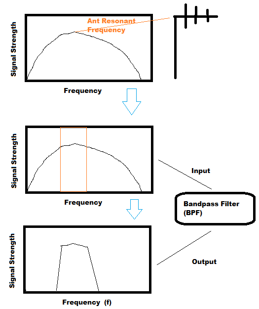
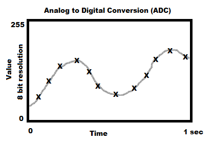
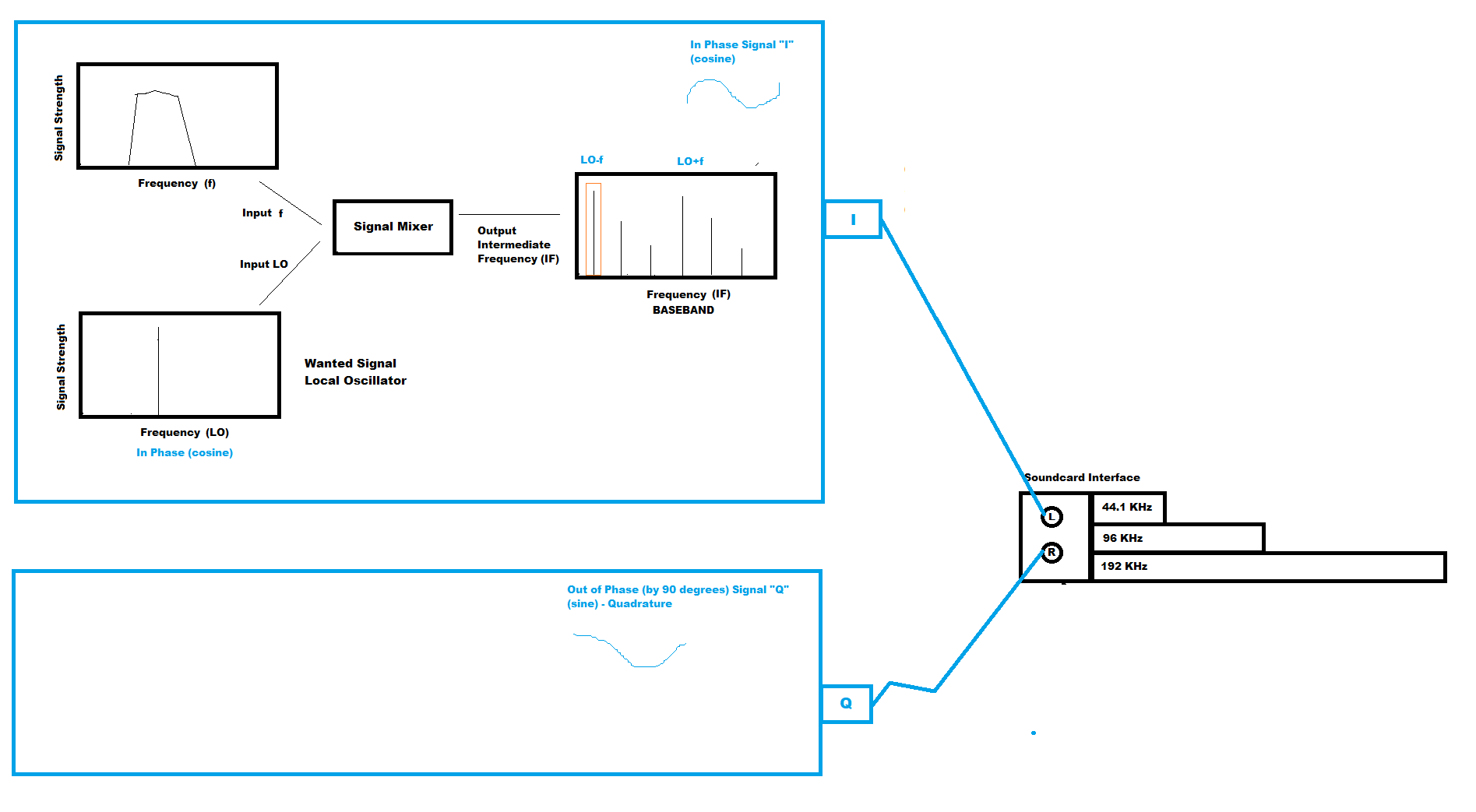
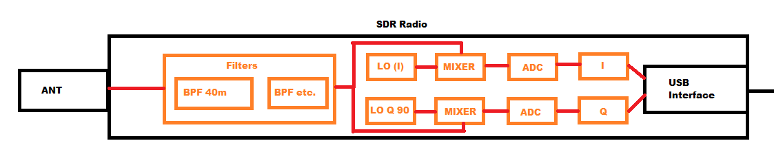
Sketches of the path from the antenna, through the filter and ADC, to I and Q on the USB cable.
The antenna and band-pass filter
An antenna is resonant (tuned) to a specific part of the electromagnetic spectrum, giving the best collection of the electric field at that frequency. That voltage, as an alternating sine wave, travels down the coax to a band-pass filter that blocks the unwanted parts of the spectrum and leaves the wanted signal.
Analogue to digital conversion (ADC)
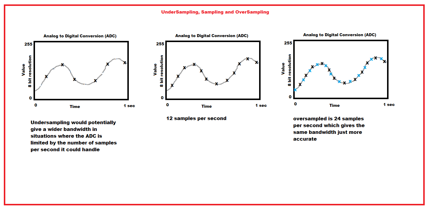
The analogue sine wave is sampled at regular time intervals. Each voltage is stored as a number from 0 to 255 if using 8 bits (a couple of nibbles, e.g. 1010 1010).
The signal mixer
The mixer takes the real radio signal from the antenna and combines it with the local oscillator (which sets the wanted frequency). It produces a suite of output signals that form the intermediate frequency (baseband), passed to the computer over USB. This is done twice: once in phase (“I”) and once out of phase (“Q”). Quadrature fixes the problem of not knowing whether the wanted signal sits above or below the oscillator frequency.
The USB SDR radio
A typical SDR samples analogue voltages after filtering, using ADC. It usually does this twice — I and Q — and sends both streams to the computer for demodulation. After demodulation the encoded signal is ready for the listener.
Under- and over-sampling
Undersampling can give a wider bandwidth when the ADC is limited by how many samples per second it can take.
Oversampling can give a larger dynamic range between signal and noise — more detail, or resolution, in the captured signal.
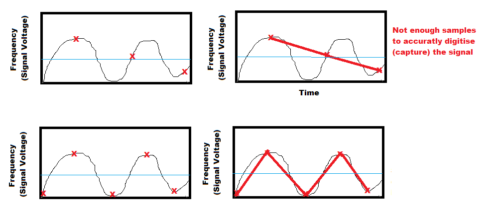
Nyquist theorem
You need twice as much sampling bandwidth as the spectrum you want to capture accurately. For 30 MHz of spectrum at once you need 60 million samples per second.